|
Here is the beginning of the
commissioned clock I am doing.
Getting the first set of transistors in place.
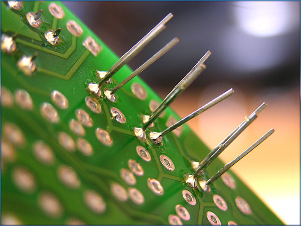
Transistor leads soldered, ready to clip the excess.
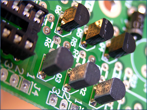
All the transistors set, soldered and done.

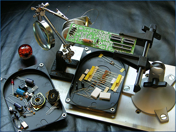
Placing the resistors, these are the most time intensive part of the circuitboard to complete. I have to make sure the values
are all correct and double check before I solder them into place.
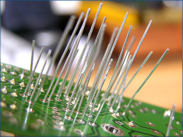
Resistors all soldered in.
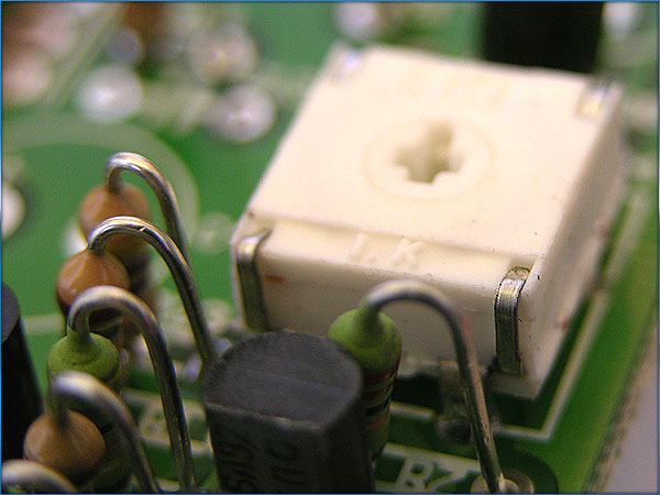
Now for the trim resistor. This is how
I adjust the voltage for the tubes. Once I power it up, I’ll have to
adjust this to somewhere between 170 and 180 volts DC. I usually set these to as close to 175 as I
can get it. It’s a very touchy
adjustment.
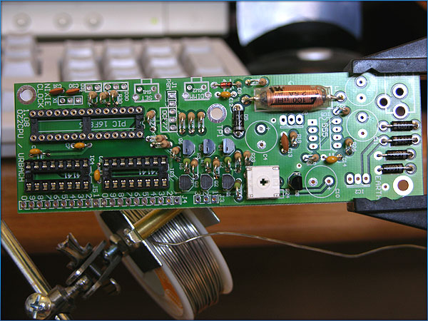
Wide shot of the board so far.
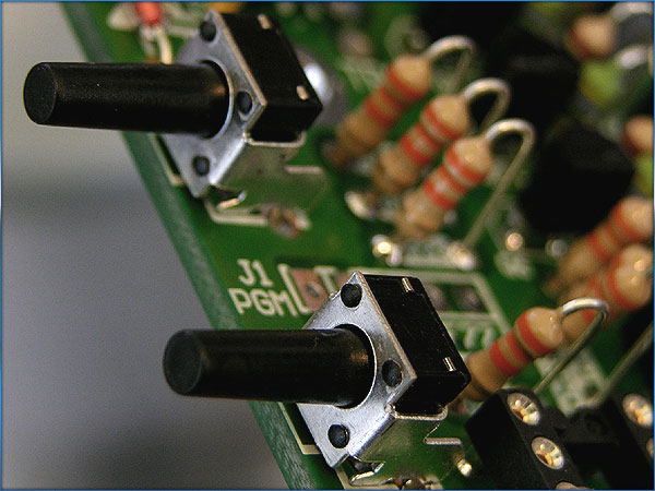
Set and Dimming buttons. These will
control the clock’s brightness and setting modes.
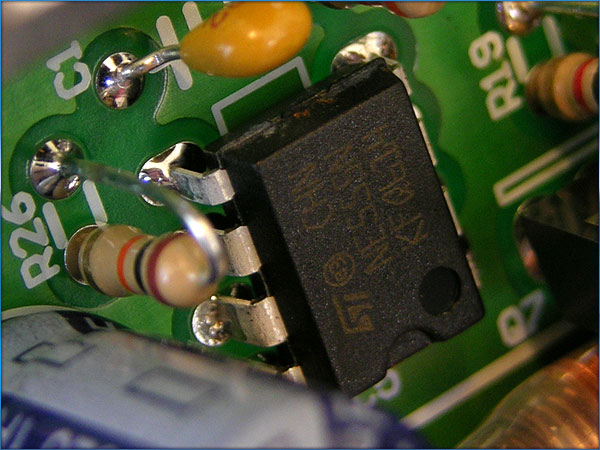
The 555 timer chip.
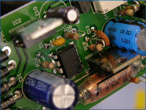
Timer chip, power transistor, regulator and large capacitors.
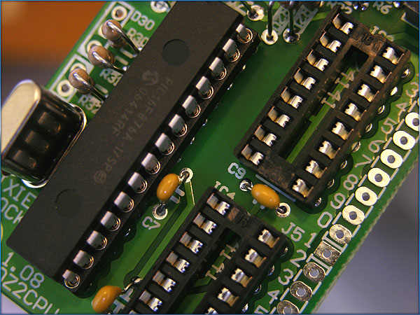
Beginning to set the PIC processor into its spot.
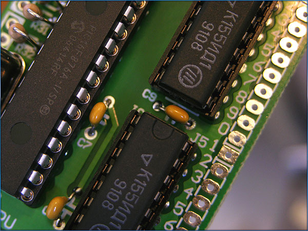
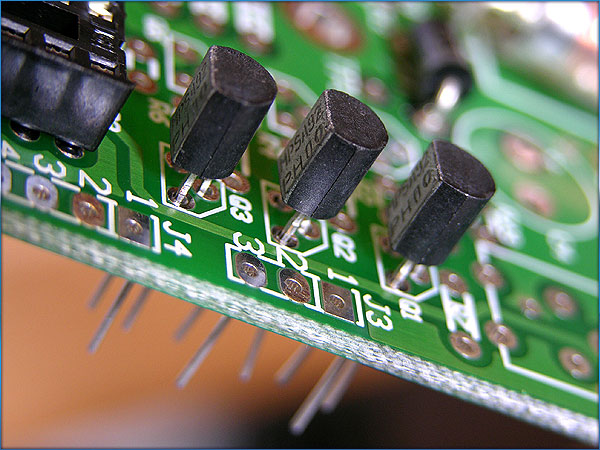
And now the Russian driver chips.
Normally, there would be six of these. One for each tube. But since we’re multiplexing these
tubes, we only need two.
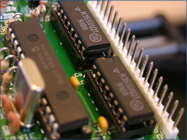
Press fitting and then soldering the pinout
connectors for the wiring harness that connects the tubes to the board.
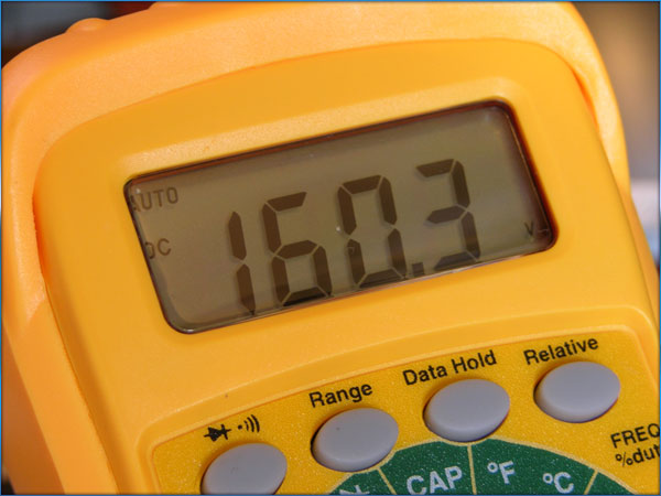
Power on! And it’s putting out
160.3 volts DC. I will adjust the trim
resistor to 175 volts.
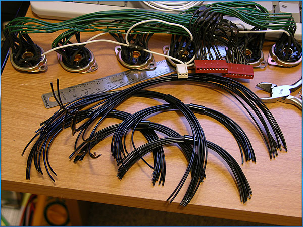
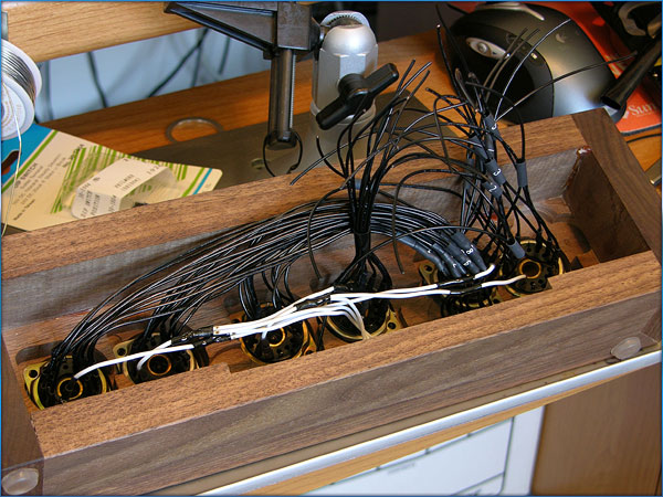
And now begins the most delicate and time consuming part of this clock. The wiring harness. Note the completed wiring harness from my
previous clock in the background. When
complete, the wiring harness will have more than 120 different solder points.
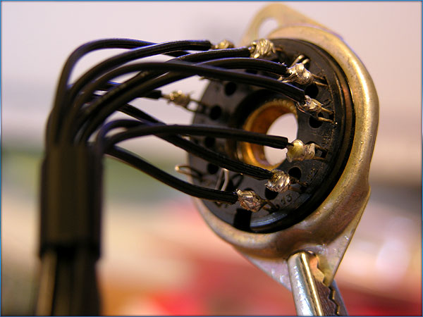
Connecting wires to the socket leads.
One through ten.
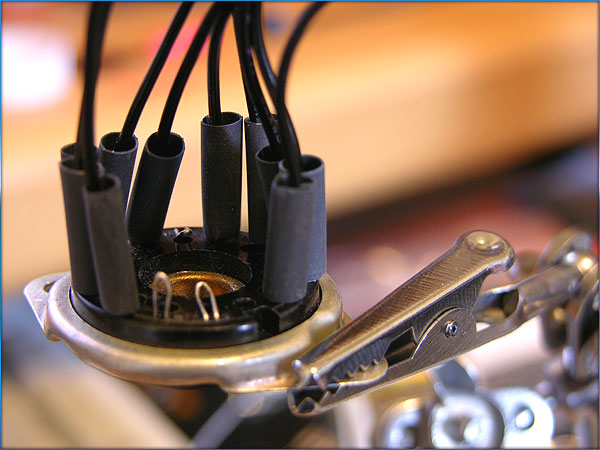
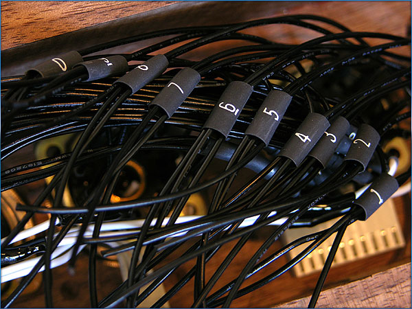
Once the cathode wires are soldered, I fit the heat shrink tubing around them
to protect against shorts and moisture.
All heat shrunk and ready to go.
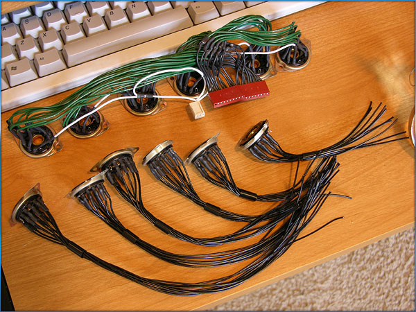
All six tube sockets and wiring for cathodes ready to go. The longest wires go to tube # six.
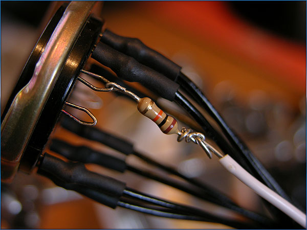
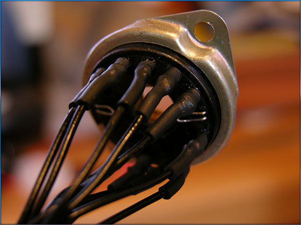
I have to solder an inline 10k resistor between the anode pin and the
controller board somewhere. I chose to
do it here next to the socket for ease of repair if need be. Once soldered and heat shrink tubing is
applied, I do the same for the other 5 tube sockets.
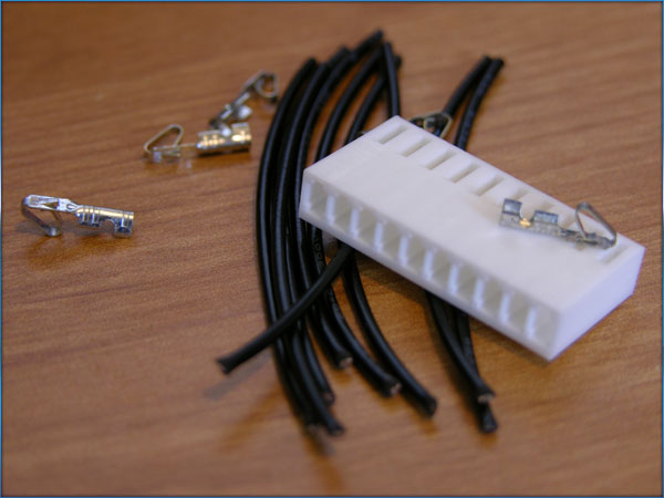
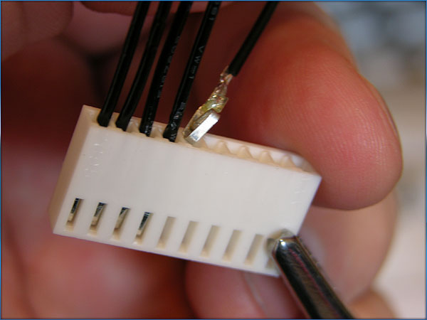
I have to make the plug that attaches to the pinout
connectors on the board. I use the
same 22 gauge wire and crimp connectors.
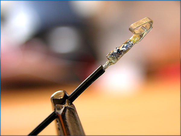
Crimping them would work, but I go the extra step of soldering them
for a secure, consistent connection.
Ready for insertion into the plug body.
15 more after this one, and I’ll have 2 plugs ready for assembly into
the wiring harness.
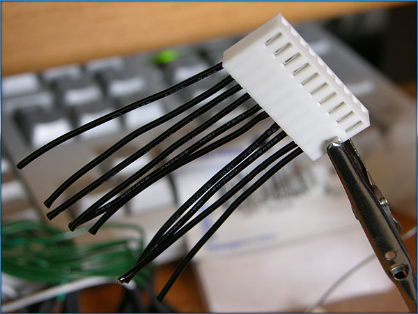
One down, one to go.
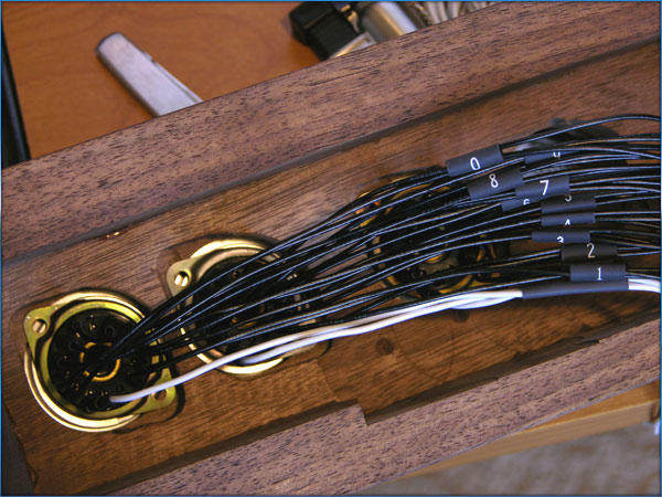
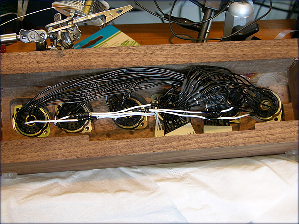
The confusing part: Keeping track of the multiplexed wires. All 70 wires have to start and end in the
correct order. Getting one of
these 140 solder points wrong could lead to numbers lighting up out
of order, or worse, a blown tube. I lay the sockets out inside my previous
clock's housing to get placement and length of leads correct.
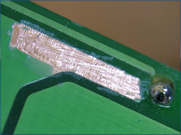
Here's where I scrape the covering off to get to the ground plate. I
need to solder in the 4 position dip switch so that the tube sleep time
may be selected.
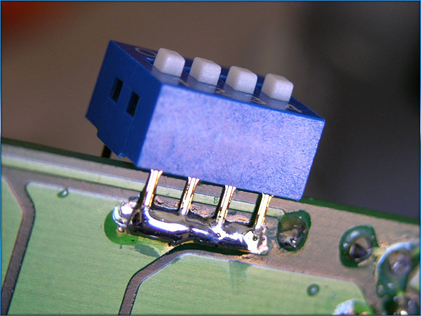
Dip switch soldered to ground.
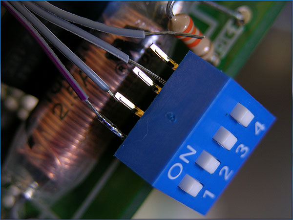
Leads coming off the switch are cut from a PC data ribbon cable.
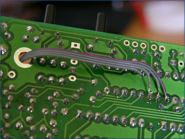
Back view of the board, where the leads from the switch ground out for
selected tube sleep times. Throw all switches, and the tubes will sleep
from 12 midnight to 6 am.
The beginning of the soldering process for the wiring harness.
This is a wiring nightmare. more than 140 different solder points that
have to be done right. I only had one in the wrong spot. I fixed that,
and it's working fine now.
Organizing the last three tubes wiring arrays.
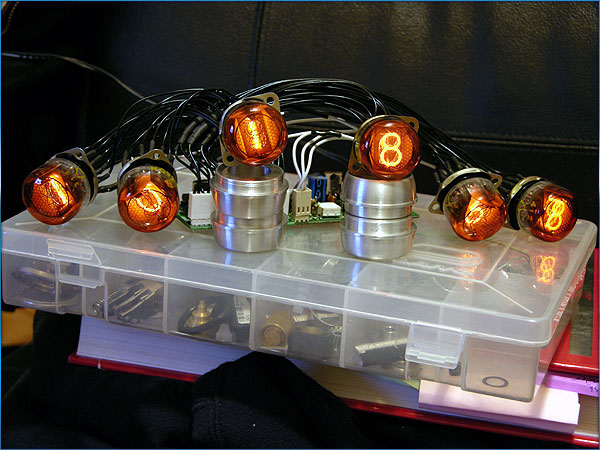
The completed wiring harness, 5 hours later.
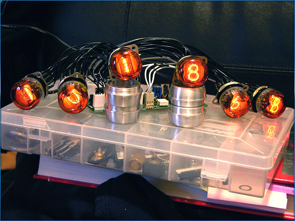
Tubes in place, the clock works! Will start on the housing soon.
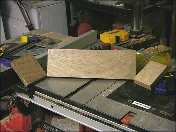
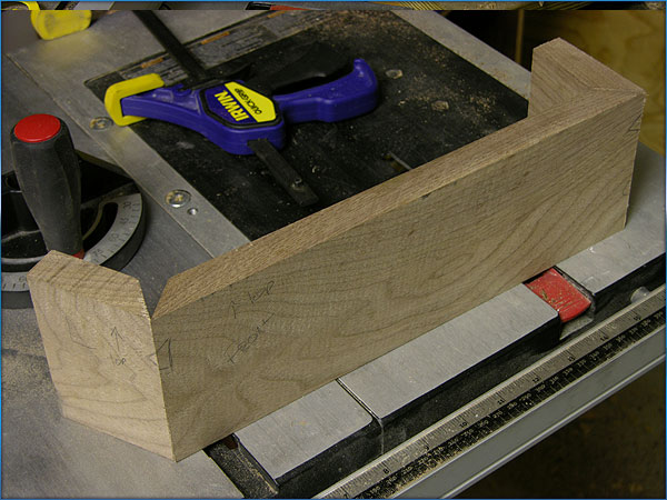
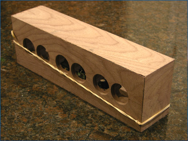
Here's the housing! At least the walnut board I will make it out of.
I have selected the grain I want, and drawn off where my cuts will be
so that the grain follows and matches around the corners.
The front and sides of the box.
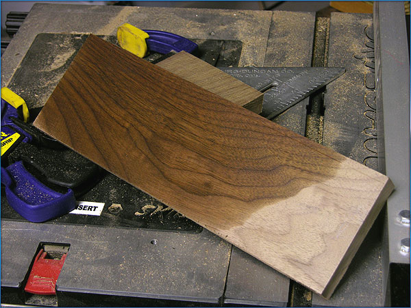
Here I pass some mineral spirits across the front to see what figuring
the grain will have once it's finished. This will evaporate, but will
give me a good idea of what the grain will look like when I am done.
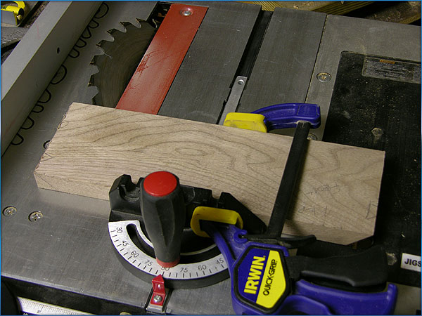
Making the 45 degree cuts for the box joints.
Grain follows around the box. Nifty!
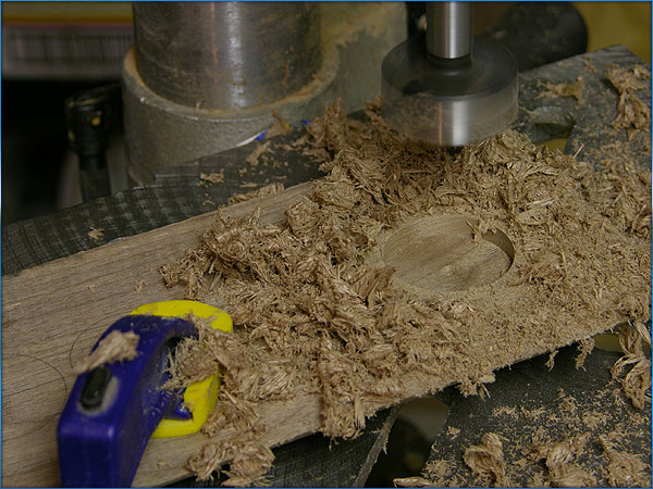
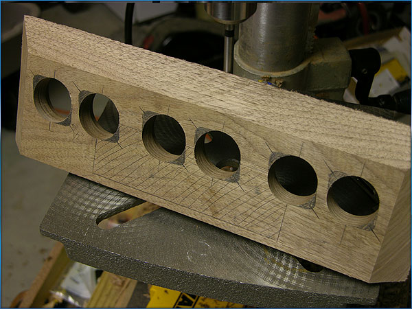
Making the first tube bezel hole.
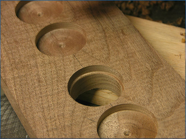
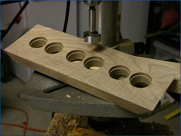
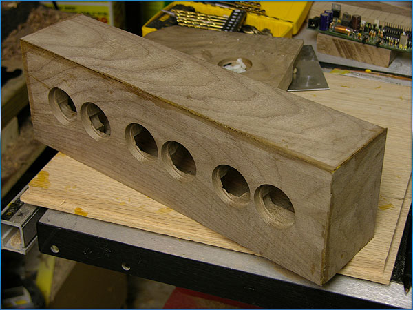
Outer holes are cut, now to drill through for the sockets.
Through cut holes are complete, now to decide how to cut away from the
back so that the sockets will fit.
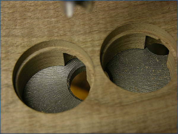
Here I have drawn where I need cuts for the sockets and the circuitboard.
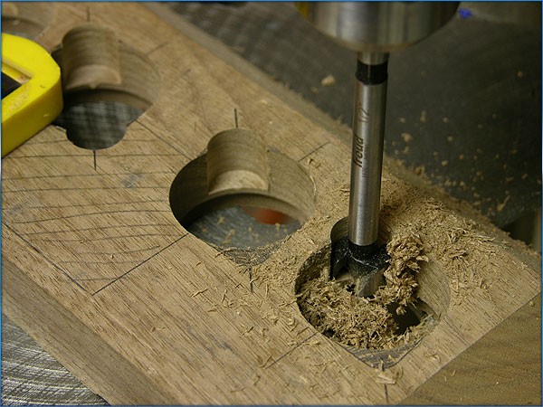
These cuts have to be very precise for correct alignment of the tubes.
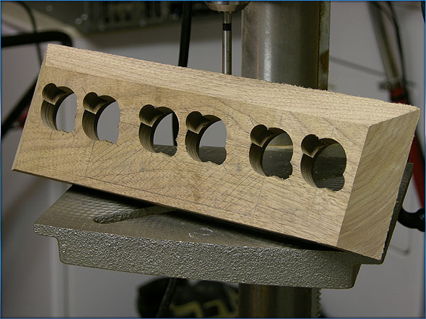
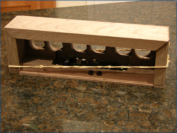
And we're almost done with the back!
Tube holes from the front of the clock.
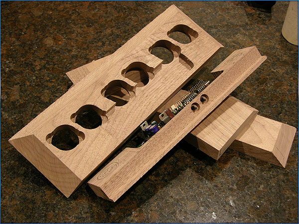
The pieces cut to spec, starting to drill out holes for buttons, routing
out the tray for the circuitboard.
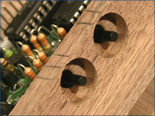
Close up of the holes for the set and dim buttons.
Laying out how I want the back panel recess to be cut. I'll make the
back panel out of aluminum.
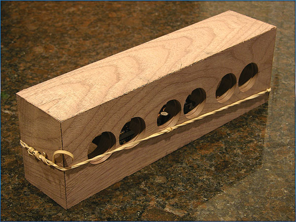
Front left grain wrap.
Front Right Grain wrap.
All glued up, ready to rough sand.
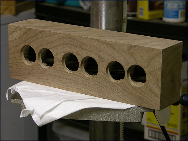
Sanding about finished, now to finish drilling the holes in the back
aluminum panel.
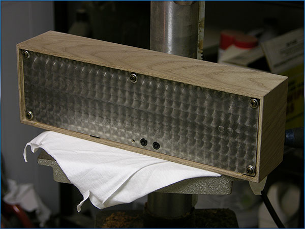
Here's the panel mounting screws and washers, I went with a antiqued
bronze screw and stainless washer.
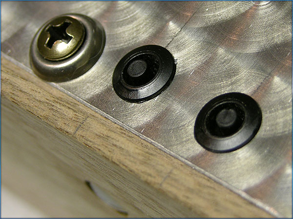
Set and Dim buttons and black plastic bezels. These bezels I salvaged
from a Dell Rack server they were throwing away at work. They previously
held status LED lights. Now they encircle the control buttons on this
clock.
|